A deeper look at the STM32F4 project template: getting things started
As promised in my post about my STM32F4 project template, I’m going to be publishing a series of posts about various interesting aspects of it. (Well, interesting to me…)
The first topic: how does the microcontroller start up and get to the point where it’s running the awesome flashing LEDs code?
Most of this is controlled by the startup assembly code, stm32f407vg.S. I didn’t write this myself – I used Philip Munts’ examples, although I did make some small changes.
Side note: different compilers have different syntaxes for assembly code. The instructions are the same for all compilers for the same processor architecture. However, how you write them might be slightly different from compiler to compiler. This is unlike languages like C++ or Ruby, where the syntax is the same everywhere. For example, some compilers denote comments with // and /* ... */ like C or C++, some use @, while others use ;. If you’re getting unexpected compiler errors, especially with things you’ve borrowed from the internet, make sure the syntax matches what your compiler expects.
Step 1: the exception vector table
If you take a look in stm32f407vg.S, you’ll see a section like this:
// Exception vector table--Common to all Cortex-M4

_vectors:   .word   __stack_end__
    .word   _start
    IRQ   NMI_Handler
    IRQ   HardFault_Handler
    IRQ   MemManage_Handler
    IRQ   BusFault_Handler
    IRQ   UsageFault_Handler
    .word   0
    .word   0
    .word   0
    .word   0
    IRQ   SVC_Handler
    IRQ   DebugMon_Handler
    .word   0
    IRQ   PendSV_Handler
    IRQ   SysTick_Handler

// Hardware interrupts specific to the STM32F407VG

    IRQ   WWDG_IRQHandler
    IRQ   PVD_IRQHandler
    IRQ   TAMP_STAMP_IRQHandler
    IRQ   RTC_WKUP_IRQHandler
    IRQ   FLASH_IRQHandler
    IRQ   RCC_IRQHandler

    ... and so on
This is where the first bit of magic happens. This sets up the exception vector table, which is what is used by the microcontroller to work out what to do when starting up. This is not something specific to the STM32F4 series – the memory layout of the table is standard for all ARM Cortex-M4 processors. It’s documented in section 2.3.4 of the Cortex-M4 Devices Generic User Guide. Note that the diagram in the documentation has the memory going from the lowest address (0x0000) at the bottom of the diagram to the highest at the top, whereas the assembly code has the lowest address first.
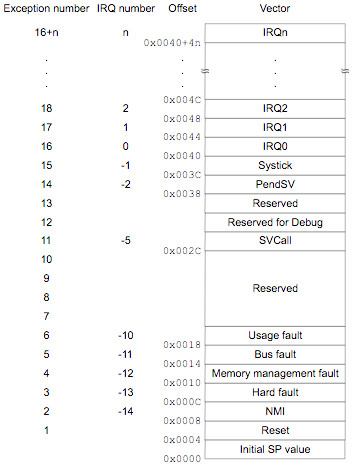 Image source: section 2.3.4 of the Cortex-M4 Devices Generic User Guide
The first entry is the initial value of the stack pointer, and here we’re initialising it to __stack_end__. Setting the initial value of the stack pointer to the end of the stack rather than the beginning may seem counterintuitive, but keep in mind that adding something to the stack decrements the stack pointer, moving it to a lower value. The value of __stack_end__ is set by the linker script, and imported into this file by the .extern __stack_end__ statement near the beginning of the file. The linker script is a topic for a whole other post, but it is worthwhile mentioning that it’s responsible for making sure the exception vector table ends up in the right place in our firmware binary, so that it ends up in the right place in memory on the device when we flash our program on to it.
(If, like me, you’re a bit rusty on what the stack pointer is and how it is used, this page has a good explanation. It talks about the MIPS architecture, but the concepts are the same for ARM and pretty much every other processor architecture.)
Next up, in the second entry (memory offset 0x0004), is the reset vector. The reset vector is a pointer to the first instruction the processor should execute when it is reset. In our case, this is _start. We’ll come back to _start in a second.
The following entries give the addresses of various interrupt handlers. ARM calls them exception vectors, hence the name ‘exception vector table’. The first few handle failure scenarios, and then the rest cover the interrupts we’re used to dealing with, such as timers. I’m not going to go into too much detail here about this here, but Philip has defined a handy IRQ macro to use to help set these up. This enables us to define handlers only for the interrupts we’re interested in – if we don’t set up a handler for a particular interrupt, it’ll use a default handler that just returns immediately.
Step 2: preparation for user code: _start
So once the processor has initialised the stack pointer with __stack_end__, it starts executing the code specified in the reset vector. As we saw before, in our case, this is _start. Philip has done a pretty good job of explaining each instruction here, so I’m not going to go through it line by line, but I will call out the rough steps:
-
copy_dataandcopy_data_loop: Copy anything in the.datasegment from flash to RAM. The.datasegment includes global and static variables that have a non-zero initial value. -
zero_bssandzero_bss_loop: Similar to the previous step, this initialises global and static variables that have a zero initial value in what is called the.bsssegment. Why are zero values handled separately to non-zero values? It saves flash memory space, and is quicker to load: it takes much less space to store that X zero values are needed and initialise that many locations to zero than it does to record zero X times and then copy all those zeroes from flash into RAM.(Wikipedia and this page both have good explanations of the
.dataand.bsssegments if you want to read more.) -
call_ctorsandctors_loop: This does what the name suggests – it calls constructors for static and global variables. -
run: The final step before we run ourmain()method is to callSystemInit().SystemInit()is a function in system_stm32f4xx.c that sets up the processor’s clock. ST provides a utility to generate this file based on your application’s requirements and hardware. (The one I’m using should be suitable for the Discovery board.)
Step 3: main()
At this point, run branches to main() and we’ve finally made it! Everything has been initialised and the processor is running our code, happily doing whatever we’ve asked of it, whether that be flashing LEDs or controlling a chainsaw-wielding drone.
Step 4: life after main()
In most applications, main() is the last stop on our journey: it will usually eventually loop forever or put the microcontroller to sleep, and so main() will never return. However, we still need to handle the case where it does return.
If it does return, the processor will execute the next instruction after the call to main():
run:
    ...other stuff in run

    bl     main                         // Call C main()
    // What's next?
If we don’t put something there, the processor could do anything – that memory location could potentially contain anything if we don’t explicitly set it to something. In our case, I’ve added an infinite loop:
run:
    ...other stuff in run

    bl     main                         // Call C main()
    // Fallthrough

loop_if_end_reached:
    b      loop_if_end_reached          // Loop forever